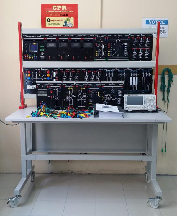
Power Electronics Trainer EM-21600Description
- Description
Description
Power Electronics has evolved from static converter technology into a significant field within electrical engineering and electronics. By using power semiconductors power electronics performs such functions as switching, controlling and converting of electrical energy with the greatest possible efficiency. One area of application for power electronics is drive technology. Here, speed variable DC and three-phase four-quadrant drives can easily be realized using modern power electronics. As a result of this development we can no longer imagine industry, workshop tools, commercial enterprises and household appliances without thyristor speed control units, smooth-starting circuits, frequency converters etc. The EDULAB DIDACTIC training panel system EM-21600Q for power electronics and drive now makes it possible to convey the technical knowledge of this field.
The experiments permit practice-oriented, hands-on training to be carried out, thus assuring the trainees of the proficiency needed to handle the tasks and the equipment found in this field. The training panels and functional units with block circuit diagrams and signal diagrams permit clear and understandable assembly of the experiment circuits. Beginning with the basic circuits, the student proceeds to tackle more complex circuits in power electronics and drive technology using a proven step-by-step method designed for didactic results. And of course, the model behind the entire system is the circuitry used in industrial applications.
Experiments cover the following topics:
Section 1: Diode and Uncontrolled Rectifier Circuit (AC-DC Conversion)
1-1 Power Diode
1-2 Single Phase Half Wave Rectifier Circuit
1-3 Full Wave Rectifier Circuit with Center Tap Transformer
1-4 Single Phase Full wave Bridge Rectifier Circuit
1-5 Three Phase Half Wave Rectifier Circuit
1-6 Three Phase Full Wave with Center Tap Transformer Rectifier Circuit
1-7 Three Phase Full Wave Bridge Rectifier Circuit
Section 2: SCR and Controlled Rectifier Circuit (AC-DC Conversion)
2-1 SCR and Single Phase Controller
2-2 Single Phase Half Wave Controlled Rectifier Circuit
2-3 Single Phase Full Wave Controlled Rectifier With Center Tap Transformer Circuit
2-4 Single Phase Bridge Full Wave Controlled Rectifier Circuit
2-5 Single Phase Full Wave Half Controlled Rectifier Circuit SCR based Inverters
2-6 Three Phase Half Wave Controlled Rectifier Circuit
2-7 Three Phase Full Wave Controlled Rectifier With Center Tap Transformer Circuit
2-8 Three Phase Bridge Full Wave Controlled Rectifier Circuit
2-9 Three Phase Full Wave Half Control Bridge Rectifier Circuit
2-10 Star-Delta Connections Control Rectifier Circuit
Section 3: Thyristors and Controlled Circuit (AC-AC Conversion)
3-1 Triac
3-2 Single Phase AC Voltage Control Circuit (On-Off Control)
3-3 Single Phase AC Voltage Control Circuit (Phase Control)
3-4 Three Phase Full Wave AC Voltage Control Circuit
Section 4: Chopper Circuit (DC-DC Conversion)
4-1 PWM Generation and Gate Drive Circuit
4-2 IGBT Chopper / Inverter Circuit
4-3 MOSFET Chopper Circuit
4-4 Darlington Chopper Circuit
4-5 Hi-Bridge Converter
EXPERIMENTS MODULE CONSISTS OF THE FOLLOWING:
| GROUP OF DIODE MODULE
EM-21-01-03 |
GROUP OF SCR MODULE
EM-21-01-05 |
||||||||||
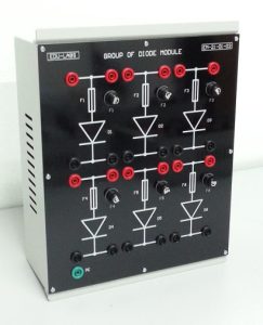
o Device : Fast Acting Silicon Diode o Quantity : 6 o Voltage : 500V o Current : 15A o Protection : 5A Fuse With Fuse Holder o Terminal Socket : 4mm Safety Type o Unit Type : Panel H2
|
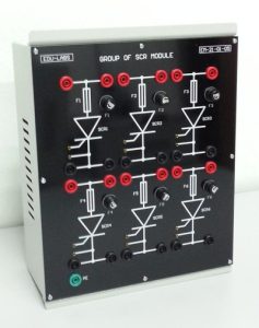
o Device : Silicon Control Rectifier o Quantity : 6 o Voltage : 600V o Current : 15A o Protection : 5A Fuse With Fuse Holder o Terminal Socket : 4mm Safety Type o Unit Type : Panel H2
|
||||||||||
| TRIAC MODULE
EM-21-01-06 |
POWER MOSFET MODULE
EM-21-01-10 |
||||||||||
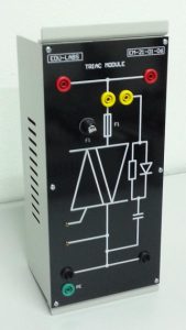
o Device : TRAIC o Quantity : 1 o Voltage : 600V o Current : 15A o Protection : 5A Fuse With Fuse Holder o Terminal Socket : 4mm Safety Type o Unit Type : Panel H1
|
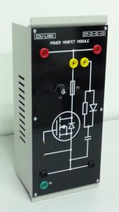
o Device : Power Field Effect Transistor (N-Channel Enhancement Mode Silicon Gate) o DC Input Voltage : Maximum 220V o DC Output Current : Maximum 5A o Switching Frequency : 0…15KHz o Quantity : 1 o Voltage : 600V o Current : 15A o Protection : 5A Fuse With Fuse Holder o Terminal Socket : 4mm Safety Type o Unit Type : Panel H1
|
||||||||||
| DARLINGTON TRANSISTOR MODULE
EM-21-01-12 |
IGBT CHOPPER / INVERTER MODULE
EM-21-01-13 |
||||||||||
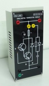
o Device : Darlington Transistor o DC Input Voltage : Maximum 220V o DC Output Current : Maximum 5A o Switching Frequency : 0…15KHz o Quantity : 1 o Voltage : 600V o Current : 15A o Protection : 5A Fuse With Fuse Holder o Terminal Socket : 4mm Safety Type o Unit Type : Panel H1
|
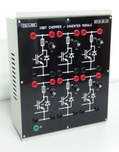
o Device : Silicon Insulated Gate Bipolar Transistor (N-Channel Enhancement Mode Silicon) o DC Input Voltage : Maximum 220V o DC Output Current : Maximum 5A o Switching Frequency : 0…15KHz o Quantity : 6 o Voltage : 600V o Current : 15A o Protection : 5A Fuse With Fuse Holder o Terminal Socket : 4mm Safety Type o Unit Type : Panel H2 |
||||||||||
| TWO PULSE CONTROLLER
EM-21-02-01 |
SIX PULSE CONTROLLER
EM-21-02-02 |
||||||||||
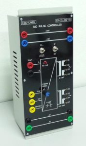
o Power Supply : +15V/0V/-15V o Input / Output : Transformer & Pulse Transformer o Synchronization Voltage : 5-220V,50/60Hz o Control Voltage : 0-10V o Trigger Angle : 0-30° o Trigger Control Delay Angle : 0-180° & 180°-360° o Pulse Output : Single Pulse, Train Pulse o Protection : 5A Fuse With Fuse Holder o Terminal Socket : 4mm Safety Type o Unit Type : Panel H1 |
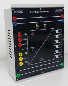
o Power Supply : +15V/0V/-15V o Input / Output : Transformer & Pulse Transformer o Synchronization Voltage : 5-400V, 50/60Hz o Control Voltage : 0-10V o Trigger Angle : 0-30° o Trigger Control Delay Angle: 0-180° & 180°-360° o Pulse Output : Single Pulse & Train Pulse o Protection : 5A Fuse With Fuse Holder o Terminal Socket : 4mm Safety Type o Unit Type : Panel H2 |
||||||||||
| PWM CONTROLLER
EM-21-02-03 |
DUTY CYCLE PHASE CONTROLLER
EM-21-02-04 |
||||||||||
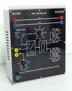
o Output: Pulse Width Modulation Isolated Pulse Output o Frequency Variable : 0…20kHz : x1, x10, x100 (Switchable) o Duty Ratio : 0…100% (Reverse / Forward) o Protection : 5A Fuse With Fuse Holder o Terminal Socket : 4mm Safety Type o Unit Type : Panel H2 |
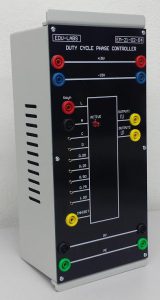
o Power Supply : +15V/0V/-15V o Synchronization Voltage : 5-400V,50/60Hz o Output Phase Control : Positive and Negative o Duty Cycle (D) : 0.00, 0.25, 0.50, 0.75, 1.00 o Protection: 5A Fuse With Fuse Holder o Terminal Socket: 4mm Safety Type o Unit Type : Panel H1
|
||||||||||
| RESISTIVE LOAD MODULE (I)
EM-21-03-01 |
INDUCTIVE LOAD MODULE
EM-21-03-02 |
||||||||||
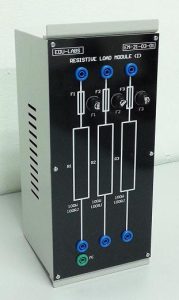
o Configuration : STAR , DELTA o Resistor : 3X100Ohm / 100 Watt o Protection : 5A Fuse With Fuse Holder o Terminal Socket : 4mm Safety Type o Unit Type : Panel H1 |
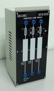
o Configuration : STAR , DELTA o Inductor : 50mH/2.5A o Protection : 5A Fuse With Fuse Holder o Terminal Socket : 4mm Safety Type o Unit Type : Panel H1 |
||||||||||
| CAPACITOR LOAD MODULE
EM-21-03-03 |
RESISTOR LOAD MODULE (II)
EM-21-03-04 |
||||||||||
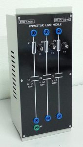
o Configuration : STAR , DELTA o Capacitor : 0.1uF / 450V o Protection : 5A Fuse With Fuse Holder o Terminal Socket : 4mm Safety Type o Unit Type : Panel H1 |
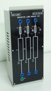
o Configuration : STAR , DELTA o Resistor : 3×1.0 Ohm/5Watt o Protection : 5A Fuse With Fuse Holder o Terminal Socket : 4mm Safety Type o Unit Type : Panel H1 |
||||||||||
| DC POWER SUPPLY MODULE
EM-21-04-02 |
CONNECTING SAFETY LEAD SET
EM-30-15-04 |
||||||||||
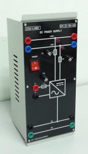
o Output Type : DC Fixed Output Voltage o Output Voltage : +15V/0/-15V o Output Current : 2A o Power Supply : 240V,50Hz o Protection : Short Circuit & 5A Fuse With Fuse Holder o Terminal Socket : 4mm Safety Type o Unit Type : Panel H1
|
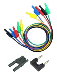
o The set consists of 2 type lead set and 2 type bridging plug set in 5 different coded colors and lengths chosen to allow the realization of all experiment manual. o Leads are capable of 15A current safety plugs. o Safety Terminal Socket (4mm): 25cm x 15 units; 50cm x 20 units; 100cm x 15 units o 2mm Test Leads Set: 45cm x 12 units o 19mm Bridging Plug Set x 10 units o 19mm Bridging Plug Set (Stackable) x 10 units |
||||||||||
| THREE PHASE AC POWER SUPPLY
EM-21-04-01 |
|||||||||||
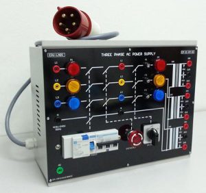 |
o Output Type : AC Fixed Output Voltage o AC Input Voltage : 3×240/415V+N+PE o Transformer Output : 3×0-45-90V o Output Current : 2.0A o Circuit Breaker, E.L.C.B, Power Switch, Emergency Switch, Pilot Lamp o Protection : Short Circuit & 5A Fuse With Fuse Holder o Terminal Socket : 4mm Safety Type o Unit Type : Panel H4
|
||||||||||
| DIGITAL DC VOLTMETER
EM-30-13-01 |
DIGITAL DC AMMETER
EM-30-13-02 |
||||||||||
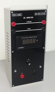
o Modular design o Measurement range : 0 ~ 600Vdc o Display : 3 ½ digits 14.2 mm LED o Accuracy : ± 0.2% ± 1 digit o Resolution : 1V o Input impedance : 1MΩ o Power source : 220Vac, 50/60 Hz o Unit Type : Panel H1 o Terminals: 4mm Safety Sockets (Color Coded) |

o Modular design o Measurement range : DC 0 ~ 10 A o Display : 3 ½ digits 14.2 mm LED o Accuracy : ± 0.3% ± 1 digit o Resolution : 0.01 A o Input impedance : < 0.1Ω o Power source : 220Vac, 50/60 Hz o Unit Type : Panel H1 o Terminals: 4mm Safety Sockets (Color Coded) |
||||||||||
| DIGITAL AC VOLTMETER
EM-30-13-03 |
DIGITAL AC AMMETER
EM-30-13-04 |
||||||||||
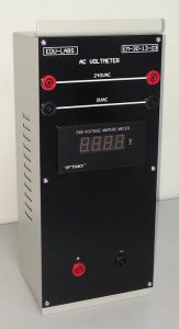
o Modular design o Measurement range : 0 ~ 600Vac o Display : 3 ½ digits 14.2 mm LED o Accuracy : ± 0.2% ± 1 digit o Resolution : 1V o Input impedance : 1MΩ o Power source : 220Vac, 50/60 Hz o Unit Type : Panel H1 o Terminals: 4mm Safety Sockets (Color Coded)
|
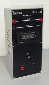
o Modular design o Measurement range : AC 0 ~ 5A o Display : 3 ½ digits 14.2 mm LED o Accuracy : ± 0.3% ± 1 digit o Resolution : 0.01 A o Input impedance : < 0.1Ω o Power source : 220Vac, 50/60 Hz o Unit Type : Panel H1 o Terminals: 4mm Safety Sockets (Color Coded) |
||||||||||
|
|||||||||||
Power Electronics Trainer EM-21600 – Objective & Experiments Lists
Experiment 1: Power Diode
Objectives: the trainee is able to
1. Describe the principle of power diode within the alternating-current circuit.
2. Determine the characteristic of power diode.
3. Determine the shape of the voltage-current characteristic curve within the alternating-current circuit for resistive load.
4. Determine the form factor.
Experiments Lists
1. Experiment 1.1: Voltage and current characteristic
2. Experiment 1.2: Determination of the shape of the voltage-current characteristic curve
3. Experiment 1.3: Determine the form factor
Experiment 2: Thyristor (SCR)
Objectives: the trainee is able to
1. Determine the shape of SCR characteristic curve
2. Describe the controlling of SCR
3. Calculate the average and RMS value of output voltage
4. Explain the correlation between phase angle of the firing pulse and output voltage
Experiments List
1. Experiment 2.1: Voltage and current characteristic of SCR
2. Experiment 2.2: Determination of the shape of the voltage-current characteristic curve of SCR
Experiment 3: Triac
Objectives: the trainee is able to
1. Determine the characteristic of triac
2. Measure the voltage in triac circuit
3. Describe the principle of triac
Experiments List
1. Experiment 3.1: Characteristic of Triac
2. Experiment 3.2: Control of the current
Experiment 4: Single Phase Half-Wave Rectifier
Objectives: the trainee is able to
1. Determine the voltage ratio for resistive load
2. Determine the shape of the voltage-current characteristic curve for resistive load
3. Determine the current ratio for resistive load
4. Determine the ripple for resistive load
5. Determine the shape of the voltage-current characteristic curve for resistive-inductive load
Experiments Lists
1. Experiment 4.1: Voltage Ratio for Resistive Load
2. Experiment 4.2: Voltage-Current Characteristic Curve for Resistive Load
3. Experiment 4.3: Current Ratio for Resistive Load
4. Experiment 4.4: Ripple Factor for Resistive Load
5. Experiment 4.5: Voltage-Current Characteristic Curve for Resistive-Inductive Load
Experiment 5: Full-wave rectifier with center tap
Objectives: the trainee is able to
1. Determine the voltage ratio
2. Measure the shape of the voltage-current characteristic curve for resistive load
3. Determine the current ratio
4. Determine the ripple for resistive load
5. Measure the shape of the voltage-current characteristic curve for resistive-inductive load
Experiments Lists
1. Experiment 5.1: voltage ratio for resistive load
2. Experiment 5.2: voltage-current characteristic curve for resistive load
3. Experiment 5.3: current ratio for resistive load
4. Experiment 5.4: Ripple factor for resistive load
5. Experiment 5.5: Voltage-current characteristic curve for resistive-inductive load
Experiment 6: Single Phase Full-Wave Bridge Rectifier
Objectives: the trainee is able to
1. Determine the voltage ratio for resistive load
2. Measure the diode voltage drop
3. Measure the shape of the current characteristic curve for resistive load
4. Determine the current ratio for resistive load
5. Determine the voltage factor for resistive load
6. Measure the shape of the voltage-current characteristic curve for resistive-inductive load
Experiments list:
1. Experiment 6.1: voltage ratio for resistive load
2. Experiment 6.2: Voltage drop on diode
3. Experiment 6.3: The shape of diode conducting current curve for resistive load
4. Experiment 6.4: Current ratio for resistive load
5. Experiment 6.5: Ripple factor for resistive load
6. Experiment 6.6: Voltage-current characteristic curve for resistive-inductive load
Experiment 7: Three Phase Half-Wave Rectifier
Objectives: the trainee is able to
1. Determine the voltage ratio for resistive load
2. Measure the shape of the current characteristic curve for resistive load
3. Determine the current ratio for resistive load
4. Determine the ripple factor for resistive load
5. Measure the shape of the voltage-current characteristic curve for resistive-inductive load
Experiments Lists
1. Experiment 7.1: voltage ratio for resistive load
2. Experiment 7.2: Voltage-current characteristic curve for resistive load
3. Experiment 7.3: Current ratio for resistive load
4. Experiment 7.4: Ripple factor
5. Experiment 7.5: Voltage-current characteristic curve for resistive-inductive load
Experiment 8: Three Phase Full-Wave Tap Rectifier
Objectives: The trainee is able to
1. Determine the voltage ratio for resistive load
2. Measure the shape of the voltage-current characteristic curve for resistive load
3. Determine the current ratio for resistive load
4. Determine the ripple factor for resistive load
5. Measure the shape of the voltage-current characteristic curve for resistive-inductive load
Experiment Lists
1. Experiment 8.1: Voltage Ratio for Resistive Load
2. Experiment 8.2: Voltage and Current Characteristic Curve for Resistive Load
3. Experiment 8.3: Current Ratio for Resistive Load
4. Experiment 8.4: Ripple Factor
5. Experiment 8.5: Voltage-Current Characteristic Curve for Resistive-Inductive Load
Experiment 9: Three Phase Full-Wave Bridge Rectifier
Objectives: the trainee is able to
1. Determine the voltage ratio for resistive load
2. Measure the shape of the voltage-current characteristic curve for resistive load
3. Determine the current ratio for resistive load
4. Determine the ripple factor for resistive load
5. Measure the shape of the voltage-current characteristic curve for resistive-inductive load
Experiments Lists
1. Experiment 9.1: Voltage ratio for resistive load
2. Experiment 9.2: Voltage characteristic curve for resistive load
3. Experiment 9.3: Current ratio for resistive load
4. Experiment 9.4: Ripple factor
5. Experiment 9.5: Voltage-current characteristic curve for resistive-inductive load
Experiment 10: Single Phase Half-Wave Controlled Rectifier
Objectives: the trainee is able to
1. Acquaint the relations between delay angle and output voltage
2. Measure the shape of the voltage-current characteristic curve for resistive load
3. Measure the shape of the voltage-current characteristic curve for resistive-inductive load
Experiments Lists
1. Experiment 10.1: The relations between delay angle and output voltage
2. Experiment 10.2: Voltage-current characteristic curve for resistive load
3. Experiment 10.3: Voltage-current characteristic curve for resistive-inductive load
Experiment 11: Full-Wave Controlled Rectifier with Center Tap
Objectives: the trainee is able to
1. Acquaint the relations between delay angle and output voltage
2. Measure the shape of the voltage-current characteristic curve for resistive load
3. Measure the shape of the voltage-current characteristic curve for resistive-inductive load
Experiments Lists
1. Experiment 11.1: The relations between delay angle and output voltage
2. Experiment 11.2: Voltage-current characteristic curve with resistive load
3. Experiment 11.3: Voltage-current characteristic curve for resistive-inductive load
Experiment 12: Single Phase Full-Wave Fully Control Bridge
Objectives: the trainee is able to
1. Acquaint the relations between delay angle and output voltage
2. Measure the shape of the voltage-current characteristic curve with resistive load
3. Measure the shape of the voltage-current characteristic curve with resistive-inductive load
Experiments List
1. Experiment 12.1: The relations between delay angle and output voltage
2. Experiment 12.2: Voltage-current characteristic curve with resistive load
3. Experiment 12.3: Voltage-current characteristic curve for resistive-inductive load
Experiment 13: Three Phase Half-Wave Control Rectifier
Objectives: the trainee is able to
1. Acquaint the relations between delay angle and output voltage
2. Measure the shape of the voltage-current characteristic curve with resistive load
3. Measure the shape of the voltage-current characteristic curve with resistive-inductive load
Experiments List
1. Experiment 13.1: The relations between delay angle and output voltage
2. Experiment 13.2: Voltage-current characteristic curve with resistive load
3. Experiment 13.3: Voltage-current characteristic curve for resistive-inductive load
Experiment 14: Three Phase Full-wave Control Rectifier with Center Tap
Objectives: the trainee is able to
1. Measure the shape of the voltage-current characteristic curve with resistive load
Experiments List
1. Experiment 14.1: Voltage-current characteristic curve with resistive load
Experiment 15: Three phase Full-Wave Fully-Control Bridge
Objectives: the trainee is able to
1. Acquaint the relations between delay angle and output voltage
2. Measure the shape of the voltage-current characteristic curve with resistive load
Experiments Lists
1. Experiment 15.1: The relations between delay angle and output voltage
2. Experiment 15.2: Voltage and line current characteristic curve
Experiment 16: Single Phase Full-Wave Half Controlled Bridge
Objectives: The trainee is able to
1. Acquaint the relations between delay angle and output voltage
2. Measure the shape of the voltage-current characteristic curve with resistive load
3. Measure the shape of the voltage-current characteristic curve with resistive-inductive load
Experiments Lists
1. Experiment 16.1: The relations between delay angle and output voltage
2. Experiment 16.2: Voltage- current characteristic curve
3. Experiment 16.3: Voltage-current characteristic curve for resistive-inductive load
Experiment 17: Three Phase Full-wave Half Control Bridge
Objectives: the trainee is able to
1. Acquaint the relations between delay angle and output voltage
2. Measure the shape of the voltage-current characteristic curve with resistive load
3. Measure the shape of the voltage-current characteristic curve with resistive-inductive load
Experiments Lists
1. Experiment 17.1: The relations between delay angle and output voltage
2. Experiment 17.2: Voltage-current characteristic curve with resistive load
3. Experiment 17.3: Voltage and line current characteristic curve for resistive-inductive load
4. Experiment 17.4: SCR current characteristic curve for resistive-inductive load
Experiment 18: Single Phase Bidirectional Connection On Resistive Load
Objectives: the trainee is able to
1. Determine the shape of the voltage and current characteristic curve at the converter on resistive load
2. Measure the shape of the SCR current characteristic curve on resistive load
3. Examine the phase control of triac
4. Indicate the control function of and
Experiments List
1. Experiment 18.1: Voltage- current characteristic curve on resistive load
2. Experiment 18.2: SCR current characteristic curve on resistive load
3. Experiment 18.3: Phase control of triac
Experiment 19: Delta–Connected Three Phase Bi-direction Connection
Experimental objectives: the trainee is able to
1. Experiment 19.1: Determine the phase control characteristic of the delta–connected three phase bidirectional connection on resistive load
Experiment 20: Star-Connected Three Phase Bidirectional Connection
Objectives: the trainee is able to
1. Determine the phase control characteristic of the star–connected three phase bidirection connection on resistive load
Experiment 21: PWM Generation Circuit
Objectives: The trainee is able to
1. Examine the produced waveform of the PWM Controller
Experiment Lists
2. Experiment 1.1: PWM Generation Circuit
Experiment 22: IGBT Chopper Circuit
Objectives: the trainee is able to
1. Acquaintance the principle of chopper circuit
2. Indicate the relationship of
3. Measure the voltage and current
4. Determine the relationship between ripple current and pulse width
Experiments list :
1. Experiment 22.1: The relationship of in IGBT chopper circuit
2. Experiment 22.2: The voltage-current characteristic curve in IGBT chopper circuit
3. Experiment 22.3: The relationship between ripple current and pulse width
4. Experiment 22.4: The relationship between ripple current and frequency
Experiment 23: MOSFET Chopper Circuit
Objectives: The trainee is able to
1. Acquaintance the principle of chopper circuit
2. Indicate the relationship of in MOSFET chopper circuit
3. Measure the voltage and current
4. Determine the relations between ripple current and pulse width
Experiment Lists
1. Experiment 23.1: The relationship of in MOSFET chopper circuit
2. Experiment 23.2: The voltage-current characteristic curve in MOSFET chopper circuit
3. Experiment 23.3: The relationship between ripple current and pulse width
4. Experiment 23.4: The relationship between ripple current and frequency
Experiment 24: Darlington Transistor Chopper Circuit
Objectives: The trainee is able to
1. Acquaintance the principle of chopper circuit
2. Indicate the relationship of in Darlington transistor chopper circuit
3. Measure the voltage and current
4. Determine the relations between ripple current and pulse width
Experiment Lists
1. Experiment 24.1: The relationship of in darlington transistor chopper circuit
2. Experiment 24.2: The voltage-current characteristic curve in darlington transistor chopper circuit
3. Experiment 24.3: The relationship between ripple current and pulse width
4. Experiment 24.4: The relationship between ripple current and frequency
Experiment 25: Cycloconverters
Experimental objectives: the trainee is able to
1. Acquaintance the principle of cycloconverters
2. Measure the output voltage on resistive load
Experiment 26: H-Bridge Converter
Objectives: The trainee is able to
1. Acquaintance the principle of H-Bridge converter
2. Measure the quantities and direction of output voltage and current
Experiments Lists
1. Experiment 26.1: The output voltage of H-Bridge converter
2. Experiment 26.2: The output current of H-Bridge converter
Note: Layout and specification may change without prior notices for products continuous development and improvement process.

