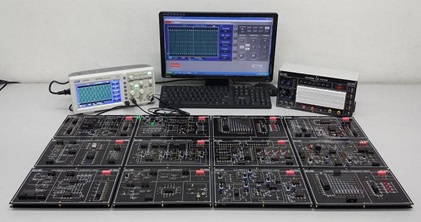
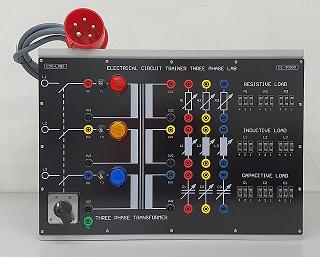
OP-AMP Trainer EE-2900Description
- Description
Description
Features:
• 9 Experiments Modules covered over 50 experiments detailed in the comprehensive experiment manual covering OP-Amp. characteristics and various application circuits
• Main unit contains ±DC power supply, signal generator etc. needed for experiments
• Covers wide ranging experiments from OP Amp characteristics to precision instrumentation amplifiers.
• Modules and the manuals are designed to ensure easy and time effective learning.
• Each module contains the experiment circuit which is clearly illustrated by a circuit diagram on its top panel.
• Switch faults are also incorporated into the modules for simulating fault situations.
Main Unit
The main unit incorporates all necessary equipment for use with the eleven modular experiments modules. Power supply, function generator, and analogue and digital meters are all built-in.
The DC power supply provides fixed ±5V
and ±12V at 1A, a variable ±0V ~ ±25V
at 1A, and a transformer provides a
19V-15V-9V-0V-9V-15V-19V AC output
at up to 1A.
The function generator offers sine, square,
and triangle waveforms at frequencies from
10Hz ~ 1MHz in 6 ranges.
The full list of experiments performed using the above modules and detailed in the experiment manual are:
OPT-EM01: Transistor Amplification Circuits Experiments Module
a) Common emitter transistor amplification circuit
b) Common base transistor amplification circuit
c) Common collector transistor amplification circuit
d) Switching type transistor circuit
e) Darlington’s circuit
OPT-EM02: FET Amplification Circuits Experiments Module
a) JFET common source amplification circuit: self-bias
b) JFET common source amplification circuit: divide-bias
c) JFET drain source amplification circuit: self-bias
d) JFET drain source amplification circuit: divide-bias
e) MOSFET amplification circuit: biased
OPT-EM03: Multi-Stage Amplification Circuits Experiments Module
a) RC coupled amplification circuit
b) Direct coupled amplification circuit
c) Transformer coupled amplification circuit
d) Push-pull amplification circuit
e) OTL amplification circuit
f) OCL amplification circuit
g) IC amplification circuit
OPT-EM04: Transistor Negative Feedback Circuits Experiments Module
a) Serial Voltage negative feedback circuit
b) Parallel Voltage negative feedback circuit
c) Serial current negative feedback circuit
d) Parallel current negative feedback circuit
OPT-EM05: Transistor Positive Feedback Circuits Experiments Module
a) Low frequency sine wave oscillating circuit
a. RC phase-shifting oscillating circuit
b. Wien bridge oscillator circuit
b) High frequency sine wave oscillating circuit
a. Hartley oscillator circuit
b. Colpitts oscillator circuit
c) Crystal oscillating circuit
d) Astable oscillating circuit
e) Monostable oscillating circuit
f) Bistable oscillating circuit
g) Intermittent oscillating circuit
h) Schmitt’s trigger circuit
i) Sawtooth wave oscillating circuit
OPT-EM06: Op-Amp Amplification Characteristics Experiments Module (1)
a) Transistor differential amplification circuit
b) Characteristics of op-amps
a. Input impedance measurement
b. Output impedance measurement
c. Bandwidth measurement
d. Slew rate measurement
e. Offset Voltage measurement (1)
f. Offset Voltage measurement (2)
OPT-EM07: Op-Amp Amplification Characteristics Experiments Module (2)
a) Inverse amplification
b) Non-inverse amplification
c) Voltage-follower circuit
d) Difference amplification (subtractor)
e) Sum amplification (adder)
f) Clipping circuit
g) Constant Voltage circuit
h) Constant current circuit
i) Differential circuit
j) Integrator circuit
OPT-EM08: Op-Amp Application Circuits Experiments (1) Experiments Module
a) Logarithm amplification circuit
b) Exponential amplification circuit
c) Peak value detection circuit
d) Precision clipping circuit
e) Voltage regulator circuit
f) Sampling/hold circuit
g) Instrument amplification circuit
h) High pass amplification circuit
i) Low pass amplification circuit
j) Band pass amplification circuit
k) RIAA amplifier circuit
l) Tone controller circuit
m) Single power inverse amplification circuit
OPT-EM09: Op-Amp Oscillating Circuit – Positive Feedback Experiments Module
a) Comparator
b) Schmitt trigger
c) Window type comparator
d) Monostable multivibrator
e) Astable multivibrator
f) Sine wave oscillation circuit
a. RC oscillator
b. Wien oscillator
MAIN UNIT SPECIFICATIONS
1. DC Power Supplies Module
Fixed Output: +5V/0.5A, -5V/0.5A, +12V/0.5A, -12V/0.5A
Variable Output: +0V ~ +23V/0.5A, -0V ~ -23V/0.5A
2. AC Power Supplies Module
19V–15V–9V–0V–9V–15V-19V
3. Function Generator Modules
Sine, Triangle and Square waveform output
Frequency range: 1Hz to 1MHz in 6 decades
With fine adjust, Amplitude and DC offset control
TTL Mode: 1Hz to 1MHz in 6 decades
Six frequency ranges:
1Hz to 10Hz
10Hz to 100Hz
100Hz to 1KHz
1KHz to 10KHz
10KHz to 100KHz
100KHz to 500KHz
Sine wave output: 0 to 12V peak to peak variable
Triangle wave output: 0 to 8V peak to peak variable
Square wave output: 0 to 22V peak to peak variable
4. Removable Solderless Breadboard Module
Interconnected nickel plated with a total of 2200 tie points nickel plated contact, fitted all DIP sizes and all components with lead and solid wire in diameter of AWG #22-30 (0.3-0.8mm)
5. Two Logic Output Switches Module
Provide two sets of logical output &
6. Two Pulse Switches Module
Provide two sets of pulse output &
2 units push button switch contain switches debouncer for eliminating the bounce caused by switch from “open” to “close” or from “close“ to “open” position.
7. 16-Bits LED Indicators with buffer Module
Sixteen LED’s separate input terminals in three colors. (RED, Yellow & Green). The LED will be lighted up when input is at “HI Level”, and it will be turned off when it is at no input or at “LO Level”. Capable for Traffic Light Experiments.
8. 16-Bits HI/LO Data Output Switches Module
16 units slide switches and corresponding output terminals. When switch is set at “down” position, the output is LO level; contrarily, it is to be HI level when setting at “up” position.
9. TTL/CMOS Selection Switch
Select TTL or CMOS Mode for data switches
10. Two digits 7-segment LED Display Module
Numerical designs and resultant display
11. Speaker Module
8Ohm, 0.25W with Audio Amplifier
12. Potentiometer Module
With 1K, 100K and 500K Ohm Potentiometers
13. Adaptors Module
2 Channels 4mm Banana and 2 Channels BNC Adaptor
The ADT-7000 is shipped with a comprehensive CD Format Experiments Manual, Instruction Manual with Self Maintenance Guide and a power cord.
Power Supply: 240VAC, 50Hz (Fused Protected)
Dimensions: (W x D x H) 550 x 280 x 90mm
Weight: 8 kgs
Note: Due to products continuous development process, layout and specification may change without prior notices.


