AC Electrical Drive Trainer C/W Scada/RTU EM-68280QDescription
- Description
Description
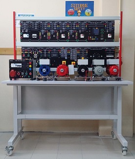
The EDU-LABS EM-68280Q system consists of a series of modular slot-in panels modules housed in a compact epoxy coated casing. Each modules represents one or more electrical / electronic components or on block diagram of a complex circuits. All functional parts of the components are mounted inside the modules with circuit symbols/mimic diagrams screen printed on the front PCB panel and terminated at 4mm safety sockets for student experimental practice.
The machines are basically industrial models, self protect kind, with coupling half-joint, especially equipped to be suitable for student training in laboratory. For this purpose the winding ends are connected to 4 mm safety socket in a metal housing on top of which a clear synoptic diagrams as educational terminal board. The student can easily understand operation and winding connection. Also most of accessories and instruments designed in Panel System A4 high in standard.
All modular slot-in panels modules are inter connecting together by using 19mm short circuit shunt and / or 4mm stackable safety test leads sets to form the desired control circuits.
LEARNING OUTCOMES
1. LEARNING OUTCOMES (AC MOTORS)
Upon completion of this course, students able to:-
1.1 Understand types of AC motor
1.1.1 Describe asynchronous motor – squirrel cage rotor
1.1.2 Describe asynchronous motor – wound (slip ring) rotor
1.1.3 Describe synchronous motor
1.2 Study the structure of asynchronous motor
1.2.1 Describe rotor and types of rotor in induction motor
1.2.2 Explain connection of the rotor in induction motor
1.2.3 Compare between squirrel cage rotor and wound (slip ring) rotor
1.2.4 Describe stator
1.2.5 Explain connection of the stator in star and delta connection
1.3 Understand the basic of AC motor
1.3.1 Define synchronous speed, slip and slip frequency
1.3.2 Determine synchronous speed (Ns)
1.4 Know the methods of AC motor control
1.4.1 Compare the characteristics of AC motor control by varying
a. Voltage
b. Frequency
c. Number of poles
d. Rotor’s resistance
1.5 Understand torque-speed curve
1.5.1 Construct the torque-speed curve for induction motor
1.6 Understand current-speed curve
1.6.1 Sketch the shape of current versus speed curve for induction motor
1.6.2 State the effects on the current-speed curve when stator voltage and frequency are varied at the same rate
1.7 Understand methods of starting a motor
1.7.1 Explain briefly method of starting a motor
a. Star
b. Delta
c. Soft Start
d. Rotor Resistance
e. Variable Frequency Drive
1.7.2 Capacitor Start & Capacitor Run Connection and Motor Direction Control
a. Forward Direction
b. Reverse Direction
1.8 Understand methods of slowing down a motor
1.8.1 Explain the methods of controlling a motor
a. Plugging
b. Jogging / Inching
c. Regenerating braking
EXPERIMENTS MODULE
| THREE PHASE INDUCTION MOTOR
EM-30-02-01 |
THREE PHASE SLIP RING MACHINE
EM-30-02-02 |
|||
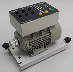
· Nominal Power: 370W (1/2HP) · Nominal Voltage: 690V / 450V (Delta/Star) · Nominal Current: 1.25A / 1.35A (Delta/Star) · Nominal Speed: 1500 rpm · Frequency: 50Hz · Cooling Method: Self Cooling · Terminals: 4mm Safety Socket · Base Plate: Attachable To Break Load Unit |
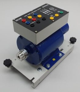
· Nominal Power: 370W (1/2HP) · Nominal Voltage: 240 / 415V (Delta/Star) · Nominal Current: 4.5 / 4.0A (Delta/Star) · Nominal Speed: 1500 rpm. · Frequency: 50Hz · Cooling Method: Self Cooling · Terminals: 4mm Safety Socket · Base Plate: Attachable To Break Load Unit |
|||
| THREE PHASE SYNCHRONOUS MACHINE
EM-30-03-02 |
SINGLE PAHSE INDUCTION MOTOR
EM-30-04-03 |
|||
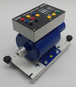
· Nominal Power: 350W (1/2HP) · Nominal Voltage: 240 / 415 V (Delta/Star) · Nominal Current: 1.85 / 2.85 A (Delta/Star) · Nominal Speed: 3000 rpm · Frequency: 50 Hz · Excitation Voltage: 0 ~ 110 VDC · Excitation Current: 0.25 A · Winding Poles: 2 · Cooling Method: Self Cooling · Terminals: 4mm Safety Socket · Base Plate: Attachable To Break Load Unit |
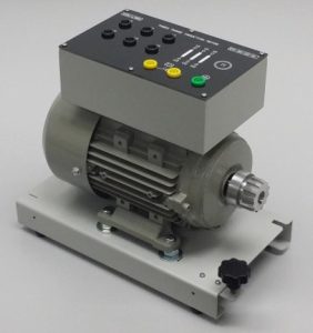
· Nominal Power: 350W (1/2HP) · Nominal Voltage: 240VAC · Nominal Current: 2.5A · Nominal Speed: 1500rpm · Frequency: 50Hz · Power Factor: 0.78 · Winding Poles: 4 · Terminals: 4mm Safety Socket · Base Plate: Attachable To Break Load Unit
|
|||
| THREE PHASE AC GENERATOR BRAKE
EM-30-06-07 |
AC/DC GENERATOR BRAKE CONTROLLER
EM-30-06-06 |
|||
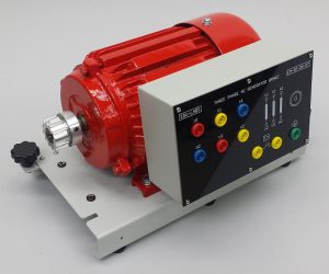
· Nominal Power: 750W (1HP) · Nominal Voltage: 415AC · Nominal Current: 2.5A · Nominal Speed: 1500 rpm. · Frequency: 50 Hz · Excitation: Permanent Magnet · Cooling Method: Self Cooling · Terminals: 4mm Safety Socket · Base Plate: Attachable To Motor Unit |
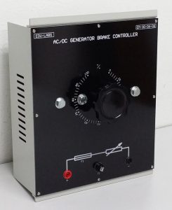
· Modular design · Suitable for all type of AC and DC Generator Brake up to 2HP · Measurement Range: 0% to 100% · Protection: Fuse · Unit Type : Panel H2
|
|||
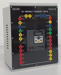
| AC VARIABLE FREQUENCY INVERTER
EM-30-14-02 |
UNIVERSAL AC/DC MOTOR
EM-30-04-05 |
|||
|
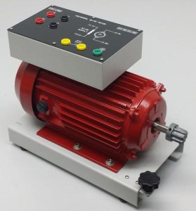
o Nominal Power: 350W (AC/DC) o Nominal Voltage: 240 V (AC/DC) o Nominal Current: 3.0 A o Nominal Speed: 3000 rpm. o Frequency: 50 Hz o Terminals: 4mm Safety Socket o Base Plate: Attachable To Break Load Unit o Coupling: EM-21-CS |
|||
| THREE PHASE POWER QUALITY METER
EM-30-13-16 |
||||
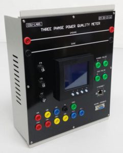
· Display Type: HD LCD Display · Real-Time Measurement o Phase voltage: V1, V2, V3, Vlnavg Line voltage: V12, V23, V31, Vllavg Current: I1, I2, I3, Iavg, In Active power: per phase and total active power Reactive power: per phase and total reactive power Apparent power: per phase and total apparent power Power factor: per phase and total power factor Total frequency · Energy And Demand o Four quadrant active energy: Import, Export, Total, Net Four quadrant reactive energy: Import, Export, Total, Net Active, Reactive, Apparent demand
|
· Power Quality Analysis
o Voltage unbalance Current unbalance o Voltage THD (Total harmonic distortion), Odd-even harmonic distortion Voltage individual harmonics, Crest factor Current THD, Odd-even harmonic distortion Current individual harmonics, K factor · Communication o Ethernet 10/100M network port o RS485 communication port o MODBUS RTU communication protocol · Trend Logging o Phase voltage Line voltage Current Active power Reactive power Apparent power Power factor Frequency Three-phase unbalance Active energy Reactive energy Apparent energy Phase · Settable Logging Interval o Logging from 1min to 60min, interval settable · Software Accessibility o 4 Tariffs (DataLog) Sharp, peak, flat, valley in different season and schedule (TOU) o Accuracy: ±0.5% o Protection: Fuse o Power Supply: AC240VAC, 50Hz o Terminals: 4mm Safety Socket |
|||
| POWER MANAGEMENT SOFTWARE
EM-30-13-16-PMS |
||||
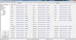 |
· PC management software; web browse data
· True-RMS measuring parameters · ANSI and IEC 0.2 accuracy class · Power quality analysis · 4 quadrant energy · Data logging · Measure individual harmonics from 2nd to 49th · TOU, 4 Tariffs, 6 Seasons, 6 Schedules |
|||
| TORQUE SENSOR MODULE
EM-30-06-18 |
TORQUE METER MODULE
EM-30-06-19 |
|||
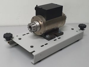
· Motor direct coupling design · Sensor Type: Noncontact rotation torque transducer · Max. torque: ±10Nm · Max Rotation speed: 12000rpm · Torque Output: Frequency · Speed Output: Frequency · Connection: Shaft and Coupling
|
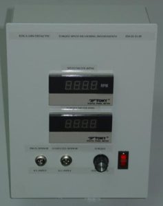
· Input: 240VAC, 50Hz 1-Phase · Unit Type: Panel H2 · Torque range: -99999-99999 N.m. · Torque display: 0-99999N.m · Speed display: 0-99999 · Power consumption: 0-99999 · Standard transmitter output: Optoelectronic isolation · Two 4mA~20mA DC current output, Output resolution ratio: 1/4000;error less than ±0.2%, F.S, loading capacity: less than 600Ω · Serial communication port as standard configuration · RS232 default setting or RS485 optional |
|||
| TORQUE MANAGEMENT SOFTWARE
EM-30-06-20 |
DIGITAL RPM METER WITH SPEED SENSOR
EM-30-13-11 |
|||
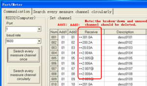
· PC management software · Data collection the measured data by computer serial port · Display and save the real-time data · Transform the saved data to TXT, EXCEL file · By curve analyses, curve print, trend browse, report generation, report edition and report print, etc.
|
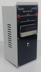
· Modular design · Display: 5 Digits · Measurement Range: 0-99999 rpm · Accuracy: ±0.1% ± 1 Digit · Power source : 240VAC, 50Hz · Unit Type : Panel H1 · Terminals: 4mm Safety Sockets · Speed Sensor: Inductive Type |
|||
| DIGITAL AC VOLTMETER
EM-30-13-03 |
DIGITAL AC AMMETER
EM-30-13-04 |
|||
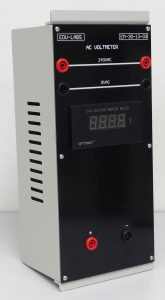
· Measurement range : AC 0 ~ 600V · Display : 3 ½ digits 14.2 mm LED · Accuracy : ± 0.2% ± 1 digit · Resolution : 1V · Input impedance : 1MΩ · Power source : 220Vac, 50/60 Hz · Unit Type : Panel H1 · Terminals: 4mm Safety Sockets (Color Coded) |
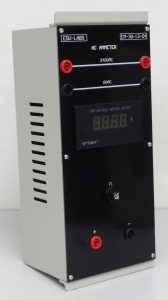
· Measurement range : AC 0 ~ 5A · Display : 3 ½ digits 14.2 mm LED · Accuracy : ± 0.3% ± 1 digit · Resolution : 0.01 A · Input impedance : < 0.1Ω · Power source : 220Vac, 50/60 Hz · Unit Type : Panel H1 · Terminals: 4mm Safety Sockets (Color Coded) |
|||
| UNIVERSAL AC/DC POWER SUPPLY
EM-30-09-02-01 |
||||
|
|
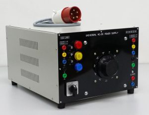
· Pilot lamps provided to indicate all live supplies. · With On/Off Switch · Fuse Protection. · Fixed Single Phase AC Power Supply: 3 x 240V AC; 8A AC (Phase To Neutral; R-N, B-N, Y-N) · Fixed Three Phase AC Power Supply: 3 x 450V AC; 8A AC (Phase To Phase; R-Y, Y-B, B-R) · Adjustable Single Phase & Three Phase AC / DC Power Supply (Simultaneously): o 3 x 0 ~ 450VAC; 8A AC (Phase To Phase) o 3 x 0 ~ 240V AC; 8A AC (Phase To Neutral) o 1 x 0 ~ 450VDC; 8A DC (DC Output) · Three Phase 5 Pin AC Plug 32A with 1.5m length 5 core power cable.
|
|||
| STAR DELTA STARTING SWITCH MODULE
EM-30-10-01 |
FORWARD REVERSING SWITCH MODULE
EM-30-10-02 |
|||
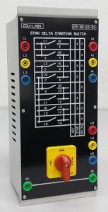
· Modular design · Switch load: 400VAC/15A · Switch positions: 0-1-2 (0-Y-∆) · Terminals : 4 mm safety sockets |
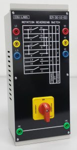
· Modular Design · Switch Load: 400VAC/15A · Switch positions: FORWARD-OFF-REVERSE · Unit Type : Panel H1 · Terminals: 4mm Safety Sockets (Color Coded) |
|||
| THREE PHASE POWER SUPPLY MODULE
EM-10-09-01 |
SELECTOR SWITCH MODULE
EM-10-05-02 |
|||
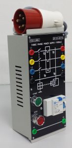
· Modular Design · Power Input: 3 Phase 240V/415V, 50Hz via input 5 core cable with 5 pin AC Plug, 32A. · Connection: 3P+N+PE. · Protection: Earth leakage circuit breaker and miniature circuit breaker · Complete with START and STOP Push Button · Three Pole ON/OFF Selector Switch. · Unit Type : Panel H1 · Terminals: 4mm Safety Sockets (Color Coded)
|
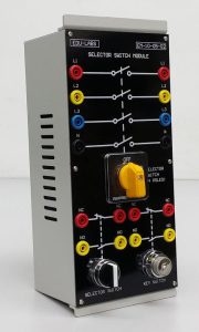
· Modular Design · Switch 1: 4 Pole Selector Switch o L1, L2, L3 and N o Switch Load: 415Vac, 10A · Switch 2: 2 Way Selector Switch o Way 1: Normally Close (NC) o Way 2: Normally Open (NO) o Switch Load: 240Vac, 5A · Switch 2: Key Switch o Way 1: Normally Close (NC) o Way 2: Normally Open (NO) o Switch Load: 240Vac, 5A · Unit Type : Panel H1 · Terminals: 4mm Safety Sockets (Color Coded) |
|||
| CIRCUIT BREAKER (3 POLES) MODULE
EM-10-01-01 |
CURRENT LIMIT PROTECTION MODULE
EM-10-04-01 (3 UNITS) |
|||
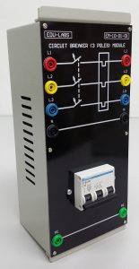
· Modular Design · Connection: 3P+N+PE · Three Pole Circuit Breaker · Switch Load: 10A · Unit Type : Panel H1 · Terminals: 4mm Safety Sockets (Color Coded)
|
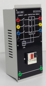
· Modular Design · Connection: 3P+N+PE. · Switch Load: 415Vac,10A · Current Setting Range: 4 ~ 6.3A (Adjustable Current Limiting) · Complete with START and STOP Push Button · Unit Type : Panel H1 · Terminals: 4mm Safety Sockets (Color Coded) |
|||
| PILOT LAMP MODULE
EM-10-10-01 |
TIMER MODULE
EM-10-07-01 |
|||
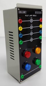
· Modular Design · 4 Units Pilot Lamp (Color: Red, Yellow, Blue & Green) · Unit Type : Panel H1 · Terminals: 4mm Safety Socket
|
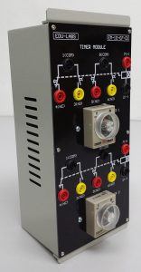
· Modular Design · Supply Voltage : 240VAC, 50Hz · Time Range : 30 Sec · Contact Rating : 240VAC, 5A · Timer : 2 Units · Timer 1 : Contact 1 (NCx1, NOx1); Contact 2 (NCx1, NOx1) · Timer 2 : Contact 1 (NCx1, NOx1); Contact 2 (NCx1, NOx1) · Unit Type : Panel H1 · Terminals: 4mm Safety Sockets |
|||
| PUSH BUTTON SWITCH MODULE (I)
EM-10-08-01 |
MAGNETIC CONTACTOR MODULE
EM-10-03-01 (3 UN ITS) |
|||
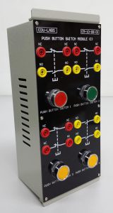
· Modular Design · Push Button Switch 1 (NCx1, NOx1) · Push Button Switch 2 (NCx1, NOx1) · Push Button Switch 3 (NCx2) · Push Button Switch 4 (NOx2) · Unit Type : Panel H1 · Terminals: 4mm Safety Socket |
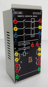
· Modular Design · 3 Pole Magnetic Contactor · Auxiliary Switch (NCx2, NOx2) · Unit Type : Panel H1 · Terminals: 4mm Safety Socket
|
|||
| POWER DRIVE (SOFT STARTERS MODULE)
EM-30-10-10 |
COUPLING HUB, NYLON SLEEVE &
SAFETY GUARD EM-30-15-03 |
|||
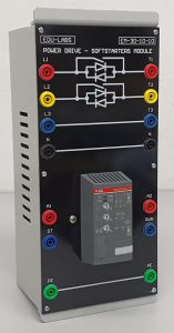
· Modular design · Modular Design · Connection: TP+N · Soft Starter: 2 Phase-Controlled 3 φ, 415V · Power Rating: 3HP, 4.8 A , Uc=110-230V AC/DC · Unit Type : Panel H1 · Terminals: 4mm Safety Socket |
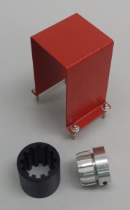 · Application: Motor & Generator · Application: Motor & Generator
· Coupling Sleeve For Mechanical Connection Of Two Electrical Machines.
|
|||
| TACHOMETER
EM-30-11-07 |
CONNECTING SAFETY TEST LEAD SET
EM-30-15-03 |
|||
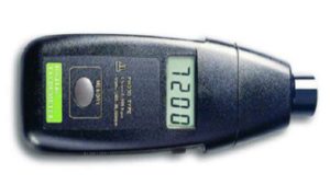
· Range: 5 to 99,999 RPM · Resolution: · 0.1RPM <1000RPM · 1RPM>1000RPM · Display: 5 Digits, 10mm (0.4”)LCD · Accuracy: ±0.05%+1 Digits · Photo Detection Distance: 50 to 150mm · Battery: 1.5V AA x 4 pcs · Memory: Last Value, Max. Value, Min. Value · Size: 190 x 72 x 37 mm |
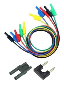
o The set consists of 2 type lead set and 2 type bridging plug set in 5 different coded colors and lengths chosen to allow the realization of all experiment manual. o Leads are capable of 15A current safety plugs. o Safety Terminal Socket (4mm): 25cm x 15 units; 50cm x 20 units; 100cm x 15 units o 19mm Bridging Plug Set x 10 units o 19mm Bridging Plug Set (Stackable) x 10 units |
|||
| AC/DC VARIABLE POWER SUPPLY
EM-30-09-04-01 |
||||
|
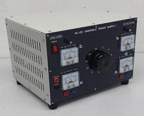
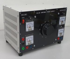
– 0 ~ 250VAC, 0 ~ 5A AC (Channel 2) Complete With AC Voltmeter & AC Ammeter – 0 ~ 250VDC, 0 ~ 5A DC (Channel 3) Complete With DC Voltmeter & DC Ammeter
|
|||
| OFF DELAY TIMER MODULE EM-10-07-02 |
RELAY MODULE EM-10-07-03 |
|||

• Modular Design |

o Modular Design |
|||
| EXPERIMENTAL TABLE
EM-30-16-01-02 |
EXPERIMENT PANEL FRAME
EM-30-16-02-02 |
|||

· 5′ Standard Desktop · Dimension: · Length : 1500mm · Width : 800mm · Height : 850mm · 3 Layer Drawer (Optional)
|

· Din Standard A4 With Two Shelves · Side Frame: T Shape · Dimension: · Length : 1450mm · Width : 20mm · Height : 300mm |
|||
Note: Due to products continuous development process, layout and specification may change without prior notices.

