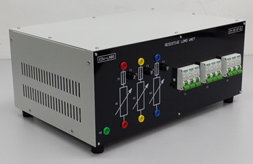
Inductive Load Unit EM-30-07-02 (300VAR)Description
- Description
Description
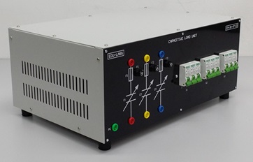
This series of Inductive Loads is designed to be used with all AC/DC Generators, Machines and Three Phase Transformer in a training environment. For this purpose the units are enclosed in metal housings and provided with Educational Terminal Boards with 4 mm safety terminals socket and clear synoptic showing the feasible connections. The units are also provided with a reference manual which illustrates their use and typical experiments.
Single-Three phase Inductive Load 7 steps variable per phase
Max Power : 3×100 VAR
Voltage : 240/415 Volt
Frequency : 50Hz
Protection : Fuse
MAIN CHARACTERISTICS
- Can be connected in Series, Parallel, Star and Delta configurations.
- Can be connected to AC Single and 3 Phase sources.
- Controlled by 3 x 3 circuit breaker switches for 7 steps selection.
TESTING DATA TABLE
At Voltage 240 Volt / Phase, 300 VARs (Max Power 3 x 100 VARs)
| No | Positions | Inductance (H) S1 | Inductance (H) S2 | Inductance (H) S3 | Power Absorbed (VARS) | ||
| SW1 | SW2 | SW3 | |||||
| 0 | OFF | OFF | OFF | – | |||
| 1 | OFF | OFF | ON | 12.65 | 12.38 | 12.46 | 18.30 |
| 2 | OFF | ON | OFF | 5.59 | 5.43 | 5.71 | 36.70 |
| 3 | OFF | ON | ON | 3.86 | 3.76 | 3.90 | 55.00 |
| 4 | ON | OFF | OFF | 3.11 | 3.18 | 3.19 | 73.30 |
| 5 | ON | OFF | ON | 2.49 | 2.62 | 2.54 | 91.70 |
| 6 | ON | ON | OFF | 1.98 | 2.05 | 2.03 | 110.00 |
| 7 | ON | ON | ON | 1.71 | 1.75 | 1.74 | 128.40 |
| No | Positions | Current (A) S1 | Current (A) S2 | Current (A) S3 | Power Absorbed (VARS) | ||
| SW1 | SW2 | SW3 | |||||
| 0 | OFF | OFF | OFF | – | |||
| 1 | OFF | OFF | ON | 0.06 | 0.06 | 0.06 | 18.30 |
| 2 | OFF | ON | OFF | 0.10 | 0.09 | 0.09 | 36.70 |
| 3 | OFF | ON | ON | 0.16 | 0.16 | 0.15 | 55.00 |
| 4 | ON | OFF | OFF | 0.22 | 0.18 | 0.18 | 73.30 |
| 5 | ON | OFF | ON | 0.27 | 0.24 | 0.25 | 91.70 |
| 6 | ON | ON | OFF | 0.32 | 0.28 | 0.26 | 110.00 |
| 7 | ON | ON | ON | 0.38 | 0.34 | 0.35 | 128.40 |
EXPERIMENTS COVER
EXPERIMENT 1: BALANCED THREE-PHASE LOADS
Experiment 1.1: Star connection with balance resistive load
Experiment 1.2: Delta connection with balance resistive load
EXPERIMENT 2: UNBALANCED THREE-PHASE LOADS
Experiment 2.1: Star connection with unbalance three-wire resistive load
Experiment 2.2: Star connection with unbalance four-wire resistive load
Experiment 2.3: Delta connection with unbalance resistive load
EXPERIMENT 3: BALANCED THREE-PHASE RL LOADS
Experiment 3.1: Star-Connected with series R-L Load
Experiment 3.2: Delta-Connected with series R-L Load
EXPERIMENT 4: BALANCED THREE-PHASE RC LOADS
Experiment 4.1: Star-Connected with series R-C Load
Experiment 4.2: Delta-Connected with series R-C Load
EXPERIMENT 5: BALANCED THREE-PHASE RLC (SERIES) LOADS
Experiment 5.1: Star-Connected with series R-L-C Load
Experiment 5.2: Delta-Connected with series R-L-C Load
EXPERIMENT 6: BALANCED THREE-PHASE RLC (PARALLEL) LOADS
Experiment 6.1: Star-Connected with parallel R-L-C Load
Experiment 6.2: Delta-Connected with parallel R-L-C Load
Note: Specification May Change Without Prior Notice For Products Continuous Development Process.


